
Debug Port Design Guide for UP/DP Systems


DPDG for UP/DP Systems Order Number: 313373-001 11
Overview
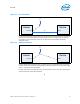
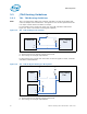
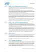
In the case of Figure 2-1 where there is a termination after the last receiver, A must be
smaller than any noted maximum routing length. This is the typical way of showing
terminations in this document. There is no restriction for the length of B unless
otherwise noted.
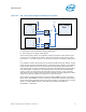
Another method for termination that is equally valid is a termination prior to the end
receiver where the maximum routing length of the signal must be less than the length
of D+C. C must be less than 200pS.
In both cases above note that there may be other devices on the A (or D) routing of the
signal if called for within this document.
§
Figure 2-1. End Termination
Device
Receiver
A
B
V
Device
Driver
Figure 2-2. Middle Termination
Device
Receiver
DC
V
Device
Driver