
Debug Port Design Guide for UP/DP Systems


DPDG for UP/DP Systems Order Number: 313373-001 13
XDP Design Guide
3 XDP Design Guide
3.1 Conventions
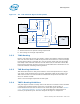
Devices in a scan chain are enumerated by tracing TDI and the scan chain’s TCK from
the XDP connector to the first device using both these signals. This device is device #0.
Then, trace TDO from device #0 to TDI of device #1, etc.
The last device in the scan chain is found by tracing TDO from the XDP connector to
TDO of the last device.
Special Note: TDI is an output of the debug port connector and TDO is an input of the
debug port connector despite their nomenclature. The opposite is true of other JTAG
devices: TDI is an input of other JTAG devices and TDO is an output.
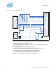
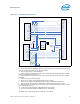
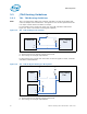
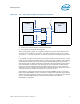
3.2 XDP Routing Overview
This section contains a thumbnail sketch of how to connect all debug port signals
except TDI/TDO in the simplest connection configuration. Please refer to the details of
each signal for complete information. These drawings represent only the most basic
connection.
TDO/TDI have a great number of options based on the number of processors in your
system and if you are allowing empty sockets. Please see Section 3.3.1, “TDI - TDO
Routing Guidelines” on page 16.
Note that any signal that is not noted on this drawing may be left as no connect.