
Debug Port Design Guide for UP/DP Systems


XDP Design Guide
16 DPDG for UP/DP Systems Order Number: 313373-001
3.3 JTAG Routing Guidelines
3.3.1 TDI - TDO Routing Guidelines
Note: TDI is an output of the debug port connector and TDO is an input of the debug port
connector despite their nomenclature. The opposite is true of other JTAG devices. TDI
is an input of other devices and TDO is an output.
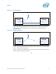
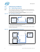
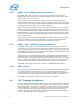
For UP systems using a single scan chain only, route TDI and TDO as indicated in
Figure 3-3. There is no need for socket bypass capability
Notes:
A - These traces have no specific routing requirements.
B - This routing has no length requirements.
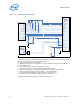
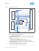
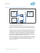
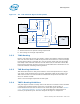
For DP systems using a single scan chain with no intent to bypass a socket, route TDI
and TDO as indicated below.
Notes:
A - These traces have no specific routing requirements.
B - This routing has no length requirements.
Figure 3-3. TDI - TDO Routing for UP Systems
51
5%
Vtt
51
5%
B
Processor
TDI
TDO
XDP Debug
Port
TDI
TDO
A
A
B
Figure 3-4. TDI - TDO No Bypass Routing for DP Systems
51
5%
51
5%
B
Proc0
TDI
TDO
XDP Debug
Port
TDI
TDO
A
A
B
Proc1
TDI
TDO
A
51
5%
B
Vtt
`
Vtt
Vtt