
Debug Port Design Guide for UP/DP Systems


DPDG for UP/DP Systems Order Number: 313373-001 21
XDP Design Guide
3.7 Observation Port Routing Guidelines
There are 4 observation ports on the XDP labeled A through D. Each observation port is
made up of 4 OBSData lines and 2 OBSFN control/strobe lines.
These lines in the past have had historical names associated with them. The OBS_Port
historically has been referred to as the BPM#[0:5] pins.
For reference: OBSFN_x0=BPM5#=PREQ#; OBSFN_x1=BPM4#=PRDY#;
OBSDATA_x3=BPM0#; OBSDATA_x2=BPM1#; OBSDATA_x1=BPM2#;
OBSDATA_x0=BPM3#
3.7.1 Observation Port Configurations
In a uniprocessor system, the OBS port signals must be routed only to Port A. In DP or
MP systems there is some flexibility with which device goes to which Observation Port.
Port A and B must have devices of a UP or DP scan chain. Port A and B must have
devices of scan chain 0. Port C and D must have devices of scan chain 1. However
within each pair of ports, there is no restriction on swapping. The same port may not
service two devices nor should you connect the same device to two ports.
This means that processor0 may be routed to either port A or B and CPU1 would be
routed to the remaining port. Clarification: UP systems may only route to port A.
3.7.2 Observation Port Routing
Terminations on these signals vary based on processor. Check the documentation on
the last device on each signal to see if it has on-die termination (ODT). If it does not,
the signal requires a 51 ohm pull-ups to VTAP. Note that no termination is needed on
the debug port side of the transmission lines.
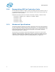
3.7.3 OBSFN_x[1:0]
Run control operations involve the assertion of signals on processor pins BPM5# and
BPM4#.
Notes:
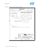
1. The traces marked ‘A’ must be length matched with other OBS signals
2. The trace lengths marked ‘A’ must not exceed 1.5ns and must be length matched to one another to within
50ps.
Figure 3-7. BPM[4:5] Routing
Processor
BPM4#
BPM5#
XDP
OBSFN_A1
OBSFN_A0
A
A
Vtt
Vtt
51 ohm
5%
51 ohm
5%