
Debug Port Design Guide for UP/DP Systems


XDP Design Guide
24 DPDG for UP/DP Systems Order Number: 313373-001
3.10 Depopulating XDP for Production Units
At some point there may be a desire to remove the debug port from production units. It
is recommended that the port real-estate and pads remain in place if they need to be
populated for a future problem.
Depopulate all physical devices (connector, termination resistors, jumpers) except:
• Termination of OBSFN_x[0:1] / BPM[4:5]# / PREQ#, PRDY#
• Termination of TCK
• Termination of TDI
• Termination of TMS
• Termination of TRSTn
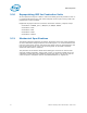
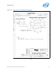
3.11 Mechanical Specifications
The following diagram illustrates the exterior dimensions of the Run Control hardware
as well as board level height restrictions and cable egress. It is recommended that the
main tool enclosure be securely attached to the target system to avoid damage to the
tool and the target system. Four 1/16” mounting holes are provided to facilitate
attachment with screws or cable ties.
The placement of the Samtec* BSH-030-01 debug port connector on the 2nd side
should be avoided if possible. Among other reasons, it should be avoided due to the
complexity of hand placing and soldering the fine pitch device. Cap all vias near the
connector pads in compliance with the Intel DFM Guidelines for capped vias.