
Debug Port Design Guide for UP/DP Systems

XDP-SSA Design Guide
30 DPDG for UP/DP Systems Order Number: 313373-001
4.10 Depopulating XDP-SSA for Production Units
At some point there may be a desire to remove the XDP-SSA from production units. It
is recommended that the port real-estate and pads remain in place if they need to be
populated for a future problem.
Depopulate all physical devices (connector, termination resistors, jumpers) except:
• Termination of OBSFN_x[0:1] / BPM[4:5]# / PREQ#, PRDY#
• Termination of TCK
• Termination of TDI
• Termination of TMS
• Termination of TRSTn
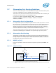
4.11 Mechanical Specifications
The following diagram It is recommended that the main XDP-SSA enclosure be securely attached
to the target system to avoid damage to the debug tool and the target system. Four 1/16” mounting
holes are provided to facilitate attachment with screws or cable ties.
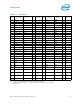
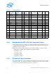
Table 4-1. XDP-SSA Pinouts
Pin Sig name
Target Sig
Name
I/O Device Pin Sig name
Target Sig
Name
I/O Device
1 OBSFN_A0 BPM[5]# I/O processor
1
Notes:
1. To the appropriate processor(s) -- see the description of each signal for more information.
2GND GND
3 OBSFN_A1 BPM[4]# I/O processor
1
4 OBSDATA_A[2] BPM[1]# I/O processor
1
5 GND GND 6 OBSDATA_A[3] BPM[0]# I/O processor
1
7 OBSDATA_A[0] BPM[3]# I/O processor
1
8GND GND
9 OBSDATA_A[1] BPM[2]# I/O processor
1
10 HOOK0 PWRGOOD I
11 GND GND 12 HOOK1 OPEN
13 HOOK4 BCLK[0] I System 14 VCC_OBS_AB Vtt I System
15 HOOK5 BCLK[1] I System 16 HOOK2 OPEN
17 GND GND 18 HOOK3 OPEN
19 HOOK6 RESET# I System 20 GND GND
21 HOOK7 front panel
reset
2
2. See specific descriptions of these signals for additional information.
O System 22 SCL 1 I/O I2C
Device
23 TDO TDO I processor
1
24 SDA 1 I/O I2C
Device
25 TRSTn TRSTn O processor
1
26 GND GND
27 GND GND 28 TCK1 open O
29 TDI TDI O processor
1
30 TCK0 TCK O processor
1
31 TMS TMS O processor
1