
Debug Port Design Guide for UP/DP Systems


DPDG for UP/DP Systems Order Number: 313373-001 33
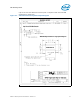
ITP700Flex Design Guide
5 ITP700Flex Design Guide
ITP700Flex is a slightly smaller connector than the XDP connector, however it has a
much smaller keep-out volume because of the connection methodology (flex edge
connector). As such many users prefer this connection method for systems that are
extremely tight on physical space such as mobile systems and blade servers.
Intel does not recommend ITP700Flex as there is a loss of capabilities with the use of
ITP700Flex and not all tools require the same termination values. These guidelines
specify the layout for most systems and notations where there may be discrepancies.
• ITP700Flex allows basic run control at a reduced rate and/or reduced edge rate
compared to XDP. The rate is dependent on many different factors that cannot be
fully covered here.
• May require the use of an adapter to convert an XDP based run control tool to an
ITP700Flex form factor connector.
• ITP700Flex may only be used on a single processor system.
Note : TDI is an output of the debug port connector and TDO is an input of the debug port
connector despite their nomenclature. The opposite is true of a processor. TDI is an
input of a processor and TDO is an output.
5.1 Conventions
The last device in the scan chain is found by tracing TDO from the XDP connector to
TDO of the last device.
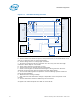
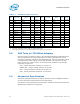
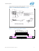
5.2 ITP700Flex Routing Overview
This section contains a thumbnail sketch of how to connect all debug port signals in the
simplest connection configuration.