
Debug Port Design Guide for UP/DP Systems


DPDG for UP/DP Systems Order Number: 313373-001 35
ITP700Flex Design Guide
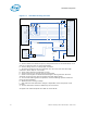
5.3 JTAG Routing Guidelines
5.3.1 TDI - TDO Routing Guidelines
Note : TDI is an output of the debug port connector and TDO is an input of the debug port
connector despite their nomenclature. The opposite is true of a processor. TDI is an
input of a processor and TDO is an output.
There is no trace length requirement for TDI/TDO. TDI termination resistor of 150
ohms 5% must be located at the processor end of the trace. TDO termination resistor
of 51 ohms 5% needs to be located at the ITP700Flex debug port end of the trace.
5.3.2 TCK Routing
Route TCK to the processor and terminate with a 27 Ohm, 1% resistor to GND. The
trace length for this signal must be a maximum of 1.5ns and must be located within
200ps of ITP700Flex debug port. Any stub on this net must be shorter than 200ps.
Suggestion: As signal integrity of TCK is one of the primary sources of run control
failures, provide a scope test point at ALL device loads (processor, debug port, etc.).
This suggestion is typically implemented only on the first spin of a system.
5.3.3 TMS Routing Guidelines
Route TMS to the processor on the scan chain and should be terminated with a 39 ohm,
1% resistor to VTAP and must be located within 200ps of ITP700Flex debug port. There
is no routing length requirements for this signal from debug port to processor
5.3.4 TRSTn Routing Guidelines
Should be routed to processor with a 500-680 Ohms 5% pull down resistor on the
trace. The location of this resistor is recommended to be near the processor with layout
described in Section 2.1.1, “Termination Resistors” on page 10 but can be placed in
other positions if necessary for platform layout. The total trace length on this signal is
unimportant.
5.3.5 FBO
FBO is routed from the processor TCK signal back to the ITP700Flex Debug Port FBO
signal with a routing length that must match the lengths of the OBS_Port within 50 ps
(see Section 5.5.1, “Observation Port Routing” on page 37).
5.3.6 Run Control Routing Guidelines
Please refer to Section 5.5.1, “Observation Port Routing” on page 37.
5.4 System Control Routing Guidelines
System Control operations report or manage the system power, scan, and reset states
of the target system. These signals are HOOK[0:7] with HOOK[0:3] generally left as
no-connects.