
Debug Port Design Guide for UP/DP Systems


DPDG for UP/DP Systems Order Number: 313373-001 37
ITP700Flex Design Guide
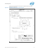
into the ICH signal SYS_RESET#. A pull-up resistor must be included on this net of 150
to 240 ohms to the Vtt voltage of the receiver. The resistor should be located near the
receiving device.
The RESET_OUT# signal has a legacy name of DBR# (Debug Port Reset).
5.5 Observation Port Routing Guidelines
These lines in the past have had historical names associated with them. For reference:
OBSFN0=BPM5=PREQ; OBSFN1=BPM4=PRDY; OBSDATA3=BPM0; OBSDATA2=BPM1;
OBSDATA1=BPM2; OBSDATA0=BPM3.
5.5.1 Observation Port Routing
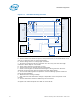
All signals from the single OBS port (OBSDATA[0:3] & OBSFN[0:1]) must be routed to
the processor BPM#[0:5]; BPM#[0:3], PREQ#, PRDY#; or OBS port pins. These
routings must be length matched to within 50 pS of one another and the longest must
not exceed 1.5nS.
Terminations on these signals vary based on processor. Check the documentation on
the last device on each signal to see if it has on-die termination (ODT). If it does not,
the signal requires a 51 ohm pull-ups to Vtap within 200 pS of that last device. Note
that no termination is needed on the debug port side of the transmission lines. No
termination is required on signals with ODT.
5.5.2 OBSFN_x[0:1]
Run control operations involve the assertion of signals on processor pins BPM5# and
BPM4#.
5.6 Power
5.6.1 VTT, VTAP
VTT and VTAP should be tied together. Within 0.1 inches of the debug port each of
these signals should have a 0.1 uF ceramic capacitor. If any of these voltages are the
same (as is the case on most processors), tie these ITP700Flex pins together at the
debug port and use only a single capacitor for that combined trace.
5.6.2 Ground
All ITP700Flex ground signals must be tied directly to the system ground with little to
no trace from the debug port.
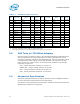
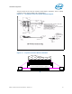
5.7 System Connection
The ITP700Flex connector is a 28 pin surface mount device -- Molex* #52435-2872 or
equivalent. Specific plating types, versions of this connector can be obtained from
Molex*. The following table documents the pinout for this connector.