
Debug Port Design Guide for UP/DP Systems


ITP700Flex Design Guide
38 DPDG for UP/DP Systems Order Number: 313373-001
5.8 XDP Tools to ITP700Flex Adapters
XDP tools require an adapter to mate to the ITP700Flex debug port. Additionally there
may be requirements of changing terminations on some signals. Below is a list of
termination resistance changes for most XDP based tools. This list is not meant to be all
encompassing but rather a guide of items that will need to be changed in all cases.
Please contact your vendor of choice for the most recent guidelines for all changes
required to use their tool.
• TCK - Change termination resistance to 51 ohm 5%
• RESET_IN# - Isolation resistor change to 1K ohm 5%
• TDI - Change termination resistance to 51 ohms 5%
• TMS - Change termination resistance to 51 ohms 5%
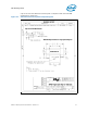
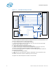
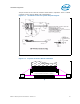
5.9 Mechanical Specifications
The following diagram illustrates the exterior dimensions of the ITP700Flex hardware
as well as board level height restrictions and cable egress.
Cap all vias near the ITP700Flex connector pads in compliance with the Intel Design For
Manufacturing Guidelines for capped vias.
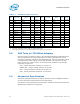
Table 5-1. ITP700Flex Debug Port Pinout
Pin Sig name
Target Sig
Name
I/O Device Pin Sig name
Target Sig
Name
I/O Device
1 TDI TDI O processor 2 TMS TMS O processor
3 TRST# TRST# O processor 4 No Connect OPEN
5 TCK0 TCK O processor 6 No Connect OPEN
7 TDO TDO I processor 8 HOOK5 BCLKn
1
Isystem
9 HOOK4 BCLKp I Clock
Generator
10 GND GND
11 FBO TCK
1
I processor
1
12 HOOK6 RESET# I system
13 OBSFN_A0 BPM[5]# I/O processor 14 GND GND
15 OBSFN_A1 BPM[4]# I/O processor 16 GND GND
17 OBSDATA_A[0] BPM[3]# I/O processor 18 GND GND
19 OBSDATA_A[1] BPM[2]# I/O processor 20 GND GND
21 OBSDATA_A[2] BPM[1]# I/O processor 22 GND GND
23 OBSDATA_A[3] BPM[0]# I/O processor 24 NC
25 HOOK7 Front panel
reset
1
O system 26 VTAP Vtt of scan
chain
27 Vtt Vtt 28 Vtt Vtt
Notes:
1. See specific descriptions of these signals for additional information
2. To the appropriate processor -- see the description of each signal for more information.