
Debug Port Design Guide for UP/DP Systems

DPDG for UP/DP Systems Order Number: 313373-001 41
Appendix A – Debug Port Interposer Considerations
A Appendix A – Debug Port
Interposer Considerations
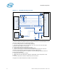
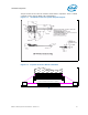
UP systems may be routed to support interposer-based run control tool debug ports.
The following pins need to be connected correctly in order for interposer-based debug
ports to function.
1. The DBR# pin of the processor must be connected to the same reset circuit as
HOOK7. In fact, as both will not be driven at the same time, connect them directly
together.
2. The ITPCLK and ITPCLK# pins of the processor must be provided a copy of
BCLK[0:1] from the system clock distribution component. It is acceptable to use
resistor stuffing on the motherboard to route a clock output from the clock
distribution component to the processor when an on-board debug port is not
populated, and route that same clock output to the on-board debug port instead if
the on-board debug port is populated.
§