
Intel 64 and IA-32 Architectures Software Developers Manual Volume 1, Basic Architecture

8-4 Vol. 1
PROGRAMMING WITH THE X87 FPU
If a load operation is performed when TOP is at 0, register wraparound occurs and
the new value of TOP is set to 7. The floating-point stack-overflow exception indicates
when wraparound might cause an unsaved value to be overwritten (see Section
8.5.1.1, “Stack Overflow or Underflow Exception (#IS)”).
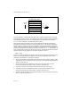
Many floating-point instructions have several addressing modes that permit the
programmer to implicitly operate on the top of the stack, or to explicitly operate on
specific registers relative to the TOP. Assemblers support these register addressing
modes, using the expression ST(0), or simply ST, to represent the current stack top
and ST(i) to specify the ith register from TOP in the stack (0 ≤ i ≤ 7). For example, if
TOP contains 011B (register 3 is the top of the stack), the following instruction would
add the contents of two registers in the stack (registers 3 and 5):
FADD ST, ST(2);
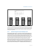
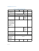
Figure 8-3 shows an example of how the stack structure of the x87 FPU registers and
instructions are typically used to perform a series of computations. Here, a two-
dimensional dot product is computed, as follows:
1. The first instruction (FLD value1) decrements the stack register pointer (TOP)
and loads the value 5.6 from memory into ST(0). The result of this operation is
shown in snap-shot (a).
2. The second instruction multiplies the value in ST(0) by the value 2.4 from
memory and stores the result in ST(0), shown in snap-shot (b).
3. The third instruction decrements TOP and loads the value 3.8 in ST(0).
4. The fourth instruction multiplies the value in ST(0) by the value 10.3 from
memory and stores the result in ST(0), shown in snap-shot (c).
5. The fifth instruction adds the value and the value in ST(1) and stores the result in
ST(0), shown in snap-shot (d).
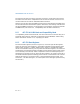
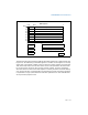
Figure 8-2. x87 FPU Data Register Stack
7
6
5
4
3
2
1
0
FPU Data Register Stack
ST(2)
ST(1)
ST(0)
Top
011B
Growth
Stack