
Intel 64 and IA-32 Architectures Software Developers Manual Volume 1, Basic Architecture

8-16 Vol. 1
PROGRAMMING WITH THE X87 FPU
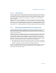
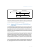
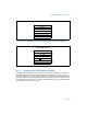
Figure 8-9. Protected Mode x87 FPU State Image in Memory, 32-Bit Format
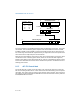
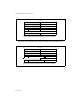
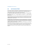
Figure 8-10. Real Mode x87 FPU State Image in Memory, 32-Bit Format
0
31
0
4
8
12
16
20
24
32-Bit Protected Mode Format
Control Word
Opcode 10...00
Status Word
Tag Word
FPU Instruction Pointer Selector
FPU Operand Pointer Selector
FPU Operand Pointer Offset
0 0 0 0 0
FPU Instruction Pointer Offset
16 15
For instructions that also store x87 FPU data registers, the eight
80-bit registers (R0-R7) follow the above structure in sequence.
031
0
4
8
12
16
20
24
32-Bit Real-Address Mode Format
Control Word
FPU Operand Pointer 31...16
FPU Instruction Pointer 31...16
Status Word
Tag Word
Opcode 10...00
0 0 0 0 0 0 0 0 0 0 0 0
FPU Operand Pointer 15...00
0 0 0 0
FPU Instruction Pointer 15...00
0 0 0 0
0
16 15
For instructions that also store x87 FPU data registers, the eight
80-bit registers (R0-R7) follow the above structure in sequence.