
Intel 64 and IA-32 Architectures Software Developers Manual Volume 1, Basic Architecture


1-4 Vol. 1
ABOUT THIS MANUAL
Appendix C — Floating-Point Exceptions Summary. Summarizes exceptions
raised by the x87 FPU floating-point and SSE/SSE2/SSE3 floating-point instructions.
Appendix D — Guidelines for Writing x87 FPU Exception Handlers. Describes
how to design and write MS-DOS* compatible exception handling facilities for FPU
exceptions (includes software and hardware requirements and assembly-language
code examples). This appendix also describes general techniques for writing robust
FPU exception handlers.
Appendix E — Guidelines for Writing SIMD Floating-Point Exception
Handlers. Gives guidelines for writing exception handlers for exceptions generated
by SSE/SSE2/SSE3 floating-point instructions.
1.3 NOTATIONAL CONVENTIONS
This manual uses specific notation for data-structure formats, for symbolic represen-
tation of instructions, and for hexadecimal and binary numbers. This notation is
described below.
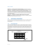
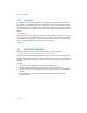
1.3.1 Bit and Byte Order
In illustrations of data structures in memory, smaller addresses appear toward the
bottom of the figure; addresses increase toward the top. Bit positions are numbered
from right to left. The numerical value of a set bit is equal to two raised to the power
of the bit position. Intel 64 and IA-32 processors are “little endian” machines; this
means the bytes of a word are numbered starting from the least significant byte. See
Figure 1-1.
Figure 1-1. Bit and Byte Order
Byte 3
Data Structure
Byte 1
Byte 2
Byte 0
Lowest
Bit offse
t
28
24
20
16
12
8
4
0
Address
Byte Offset
Highest
Address
32 24 23 16 15 8 7 0