
Intel 64 and IA-32 Architectures Software Developers Manual Volume 1, Basic Architecture

10-6 Vol. 1
PROGRAMMING WITH STREAMING SIMD EXTENSIONS (SSE)
10.2.3.1 SIMD Floating-Point Mask and Flag Bits
Bits 0 through 5 of the MXCSR register indicate whether a SIMD floating-point excep-
tion has been detected. They are “sticky” flags. That is, after a flag is set, it remains
set until explicitly cleared. To clear these flags, use the LDMXCSR or the FXRSTOR
instruction to write zeroes to them.
Bits 7 through 12 provide individual mask bits for the SIMD floating-point exceptions.
An exception type is masked if the corresponding mask bit is set, and it is unmasked
if the bit is clear. These mask bits are set upon a power-up or reset. This causes all
SIMD floating-point exceptions to be initially masked.
If LDMXCSR or FXRSTOR clears a mask bit and sets the corresponding exception flag
bit, a SIMD floating-point exception will not be generated as a result of this change.
The unmasked exception will be generated only upon the execution of the next
SSE/SSE2/SSE3 instruction that detects the unmasked exception condition.
For more information about the use of the SIMD floating-point exception mask and
flag bits, see Section 11.5, “SSE, SSE2, and SSE3 Exceptions,” and Section 12.8,
“SSE3/SSSE3 Exceptions.”
10.2.3.2 SIMD Floating-Point Rounding Control Field
Bits 13 and 14 of the MXCSR register (the rounding control [RC] field) control how
the results of SIMD floating-point instructions are rounded. See Section 4.8.4,
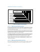
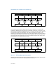
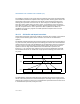
Figure 10-3. MXCSR Control/Status Register
31
16
Overflow Mask
Divide-by-Zero Mask
Denormal Operation Mask
Invalid Operation Mask
Denormals Are Zeros*
Precision Flag
Underflow Flag
Underflow Mask
Flush to Zero
Rounding Control
15
13
14 12
11 10 9
8
7
6
543
2
10
Precision Mask
Overflow Flag
Divide-by-Zero Flag
Denormal Flag
Invalid Operation Flag
F
Z
R
C
P
M
Z
E
O
E
U
E
P
E
I
M
D
M
Z
M
O
M
U
M
Reserved
D
E
E
I
D
A
Z
* The denormals-are-zeros flag was introduced in the Pentium 4 and Intel Xeon processor.