
Intel 64 and IA-32 Architectures Software Developers Manual Volume 1, Basic Architecture

Vol. 1 11-31
PROGRAMMING WITH STREAMING SIMD EXTENSIONS 2 (SSE2)
Developer’s Manual, Volume 2A, for a description of FXSAVE and the layout of the
FXSAVE image.
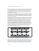
4. Check the value in the MXCSR_MASK field in the FXSAVE image (bytes 28
through 31).
— If the value of the MXCSR_MASK field is 00000000H, then the MXCSR_MASK
value is the default value of 0000FFBFH. Note that this value indicates that bit
6 of the MXCSR register is reserved; this setting indicates that the
denormals-are-zero mode is not supported on the processor.
— If the value of the MXCSR_MASK field is non-zero, the MXCSR_MASK value
should be used as the MXCSR_MASK.
All bits set to 0 in the MXCSR_MASK value indicate reserved bits in the MXCSR
register. Thus, if the MXCSR_MASK value is AND’d with a value to be written into the
MXCSR register, the resulting value will be assured of having all its reserved bits set
to 0, preventing the possibility of a general-protection exception being generated
when the value is written to the MXCSR register.
For example, the default MXCSR_MASK value when 00000000H is returned in the
FXSAVE image is 0000FFBFH. If software AND’s a value to be written to MXCSR
register with 0000FFBFH, bit 6 of the result (the DAZ flag) will be ensured of being
set to 0, which is the required setting to prevent general-protection exceptions on
processors that do not support the denormals-are-zero mode.
To prevent general-protection exceptions, the MXCSR_MASK value should be AND’d
with the value to be written into the MXCSR register in the following situations:
• Operating system routines that receive a parameter from an application program
and then write that value to the MXCSR register (either with an FXRSTOR or
LDMXCSR instruction)
• Any application program that writes to the MXCSR register and that needs to run
robustly on several different IA-32 processors
Note that all bits in the MXCSR_MASK value that are set to 1 indicate features that
are supported by the MXCSR register; they can be treated as feature flags for identi-
fying processor capabilities.
11.6.7 Interaction of SSE/SSE2 Instructions with x87 FPU and MMX
Instructions
The XMM registers and the x87 FPU and MMX registers represent separate execution
environments, which has certain ramifications when executing SSE, SSE2, MMX, and
x87 FPU instructions in the same code module or when mixing code modules that
contain these instructions:
• Those SSE and SSE2 instructions that operate only on XMM registers (such as the
packed and scalar floating-point instructions and the 128-bit SIMD integer
instructions) in the same instruction stream with 64-bit SIMD integer or x87 FPU
instructions without any restrictions. For example, an application can perform the