
Intel 64 and IA-32 Architectures Software Developers Manual Volume 1, Basic Architecture

D-2 Vol. 1
GUIDELINES FOR WRITING X87 FPU EXCEPTION HANDLERS
D.1 MS-DOS COMPATIBILITY SUB-MODE FOR HANDLING
X87 FPU EXCEPTIONS
The first generations of IA-32 processors (starting with the Intel 8086 and 8088
processors and going through the Intel 286 and Intel386 processors) did not have an
on-chip floating-point unit. Instead, floating-point capability was provided on a sepa-
rate numeric coprocessor chip. The first of these numeric coprocessors was the Intel
8087, which was followed by the Intel 287 and Intel 387 numeric coprocessors.
To allow the 8087 to signal floating-point exceptions to its companion 8086 or 8088,
the 8087 has an output pin, INT, which it asserts when an unmasked floating-point
exception occurs. The designers of the 8087 recommended that the output from this
pin be routed through a programmable interrupt controller (PIC) such as the Intel
8259A to the INTR pin of the 8086 or 8088. The accompanying interrupt vector
number could then be used to access the floating-point exception handler.
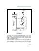
However, the original IBM* PC design and MS-DOS operating system used a different
mechanism for handling the INT output from the 8087. It connected the INT pin
directly to the NMI input pin of the 8086 or 8088. The NMI interrupt handler then had
to determine if the interrupt was caused by a floating-point exception or another NMI
event. This mechanism is the origin of what is now called the “MS-DOS compatibility
mode.” The decision to use this latter floating-point exception handling mechanism
came about because when the IBM PC was first designed, the 8087 was not available.
When the 8087 did become available, other functions had already been assigned to
the eight inputs to the PIC. One of these functions was a BIOS video interrupt, which
was assigned to interrupt number 16 for the 8086 and 8088.
The Intel 286 processor created the “native mode” for handling floating-point excep-
tions by providing a dedicated input pin (ERROR#) for receiving floating-point excep-
tion signals and a dedicated interrupt number, 16. Interrupt 16 was used to signal
floating-point errors (also called math faults). It was intended that the ERROR# pin
on the Intel 286 be connected to a corresponding ERROR# pin on the Intel 287
numeric coprocessor. When the Intel 287 signals a floating-point exception using this
mechanism, the Intel 286 generates an interrupt 16, to invoke the floating-point
exception handler.
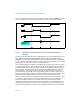
To maintain compatibility with existing PC software, the native floating-point excep-
tion handling mode of the Intel 286 and 287 was not used in the IBM PC AT system
design. Instead, the ERROR# pin on the Intel 286 was tied permanently high, and
the ERROR# pin from the Intel 287 was routed to a second (cascaded) PIC. The
resulting output of this PIC was routed through an exception handler and eventually
caused an interrupt 2 (NMI interrupt). Here the NMI interrupt was shared with IBM
PC AT’s new parity checking feature. Interrupt 16 remained assigned to the BIOS
video interrupt handler. The external hardware for the MS-DOS compatibility mode
must prevent the Intel 286 processor from executing past the next x87 FPU instruc-
tion when an unmasked exception has been generated. To do this, it asserts the
BUSY# signal into the Intel 286 when the ERROR# signal is asserted by the Intel 287.
The Intel386 processor and its companion Intel 387 numeric coprocessor provided
the same hardware mechanism for signaling and handling floating-point exceptions