
Intel 64 and IA-32 Architectures Software Developers Manual Volume 1, Basic Architecture

D-6 Vol. 1
GUIDELINES FOR WRITING X87 FPU EXCEPTION HANDLERS
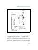
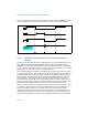
Figure D-1 is implemented. The temporal regions within the x87 FPU exception
handler activity are described as follows:
1. The FERR# signal is activated by an x87 FPU exception and sends an interrupt
request through the PIC to the processor’s INTR pin.
2. During the x87 FPU interrupt service routine (exception handler) the processor
will need to clear the interrupt request latch (Flip Flop #1). It may also want to
execute non-control x87 FPU instructions before the exception is cleared from the
x87 FPU. For this purpose the IGNNE# must be driven low. Typically in the PC
environment an I/O access to Port 0F0H clears the external x87 FPU exception
interrupt request (FP_IRQ). In the recommended circuit, this access also is used
to activate IGNNE#. With IGNNE# active, the x87 FPU exception handler may
execute any x87 FPU instruction without being blocked by an active x87 FPU
exception.
3. Clearing the exception within the x87 FPU will cause the FERR# signal to be
deactivated and then there is no further need for IGNNE# to be active. In the
recommended circuit, the deactivation of FERR# is used to deactivate IGNNE#. If
another circuit is used, the software and circuit together must assure that
IGNNE# is deactivated no later than the exit from the x87 FPU exception handler.