
Intel 64 and IA-32 Architectures Software Developers Manual Volume 1, Basic Architecture

Vol. 1 D-7
GUIDELINES FOR WRITING X87 FPU EXCEPTION HANDLERS
*
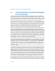
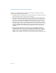
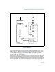
In the circuit in Figure D-1, when the x87 FPU exception handler accesses I/O port
0F0H it clears the IRQ13 interrupt request output from Flip Flop #1 and also clocks
out the IGNNE# signal (active) from Flip Flop #2. So the handler can activate
IGNNE#, if needed, by doing this 0F0H access before clearing the x87 FPU exception
condition (which de-asserts FERR#).
However, the circuit does not depend on the order of actions by the x87 FPU excep-
tion handler to guarantee the correct hardware state upon exit from the handler.
Flip Flop #2, which drives IGNNE# to the processor, has its CLEAR input attached to
the inverted FERR#. This ensures that IGNNE# can never be active when FERR# is
Figure D-1. Recommended Circuit for MS-DOS Compatibility x87 FPU
Exception Handling
,23RUW)+
$GGUHVV'HFRGH
)(55
,*11(
,175
,QWHUUXSW
&RQWUROOHU
5(6(7
)3B,54
9
35
9
9
9
35
&/5
))
))
,QWHO3URFHVVRU
3HQWLXP3URFHVVRU
3HQWLXP3UR3URFHVVRU
/(*(1'
))Q)OLS)ORSQ
&/5&OHDURU5HVHW