
Intel 64 and IA-32 Architectures Software Developers Manual Volume 1, Basic Architecture

3-18 Vol. 1
BASIC EXECUTION ENVIRONMENT
When writing application code, programmers generally create segment selectors
with assembler directives and symbols. The assembler and other tools then create
the actual segment selector values associated with these directives and symbols. If
writing system code, programmers may need to create segment selectors directly.
See Chapter 3, “Protected-Mode Memory Management,” in the Intel® 64 and IA-32
Architectures Software Developer’s Manual, Volume 3A.
How segment registers are used depends on the type of memory management model
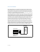
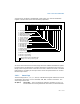
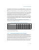
that the operating system or executive is using. When using the flat (unsegmented)
memory model, segment registers are loaded with segment selectors that point to
overlapping segments, each of which begins at address 0 of the linear address space
(see Figure 3-6). These overlapping segments then comprise the linear address
space for the program. Typically, two overlapping segments are defined: one for code
and another for data and stacks. The CS segment register points to the code
segment and all the other segment registers point to the data and stack segment.
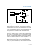
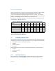
When using the segmented memory model, each segment register is ordinarily
loaded with a different segment selector so that each segment register points to a
different segment within the linear address space (see Figure 3-7). At any time, a
program can thus access up to six segments in the linear address space. To access a
segment not pointed to by one of the segment registers, a program must first load
the segment selector for the segment to be accessed into a segment register.
Figure 3-6. Use of Segment Registers for Flat Memory Model
Segment Registers
CS
SS
DS
ES
FS
GS
Linear Address
Space for Program
The segment selector in
each segment register
points to an overlapping
Overlapping
Segments
of up to
4 GBytes
segment in the linear
address space.
Beginning at
Address 0