
Intel 64 and IA-32 Architectures Software Developers Manual Volume 2A, Instruction Set Reference, A-M

3-418 Vol. 2
INSTRUCTION SET REFERENCE, A-M
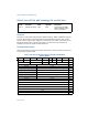
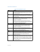
FTW x87 FPU Tag Word (8 bits). The tag information saved here is abridged, as
described in the following paragraphs. See Figure 8-7 in the Intel® 64 and
IA-32 Architectures Software Developer’s Manual, Volume 1, for the layout
of the x87 FPU tag word.
FOP x87 FPU Opcode (16 bits). The lower 11 bits of this field contain the
opcode, upper 5 bits are reserved. See Figure 8-8 in the Intel® 64 and IA-32
Architectures Software Developer’s Manual, Volume 1, for the layout of the
x87 FPU opcode field.
FPU IP x87 FPU Instruction Pointer Offset (32 bits). The contents of this field
differ depending on the current addressing mode (32-bit or 16-bit) of the
processor when the FXSAVE instruction was executed:
32-bit mode — 32-bit IP offset.
16-bit mode — low 16 bits are IP offset; high 16 bits are reserved.
See “x87 FPU Instruction and Operand (Data) Pointers” in Chapter 8 of the
Intel® 64 and IA-32 Architectures Software Developer’s Manual, Volume 1,
for a description of the x87 FPU instruction pointer.
CS x87 FPU Instruction Pointer Selector (16 bits).
FPU DP x87 FPU Instruction Operand (Data) Pointer Offset (32 bits). The contents
of this field differ depending on the current addressing mode (32-bit or 16-
bit) of the processor when the FXSAVE instruction was executed:
32-bit mode — 32-bit IP offset.
16-bit mode — low 16 bits are IP offset; high 16 bits are reserved.
See “x87 FPU Instruction and Operand (Data) Pointers” in Chapter 8 of the
Intel® 64 and IA-32 Architectures Software Developer’s Manual, Volume 1,
for a description of the x87 FPU operand pointer.
DS x87 FPU Instruction Operand (Data) Pointer Selector (16 bits).
MXCSR MXCSR Register State (32 bits). See Figure 10-3 in the Intel® 64 and IA-32
Architectures Software Developer’s Manual, Volume 1, for the layout of the
MXCSR register. If the OSFXSR bit in control register CR4 is not set, the
FXSAVE instruction may not save this register. This behavior is
implementation dependent.
MXCSR_
MASK
MXCSR_MASK (32 bits). This mask can be used to adjust values written to
the MXCSR register, ensuring that reserved bits are set to 0. Set the mask
bits and flags in MXCSR to the mode of operation desired for SSE and SSE2
SIMD floating-point instructions. See “Guidelines for Writing to the MXCSR
Register” in Chapter 11 of the Intel® 64 and IA-32 Architectures Software
Developer’s Manual, Volume 1, for instructions for how to determine and
use the MXCSR_MASK value.
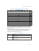
Table 3-49. Field Definitions (Contd.)
Field Definition