
Intel 64 and IA-32 Architectures Software Developers Manual Volume 2A, Instruction Set Reference, A-M

Vol. 2 3-15
INSTRUCTION SET REFERENCE, A-M
assignments are described in the “Operation” section. The values of flags listed as
undefined may be changed by the instruction in an indeterminate manner. Flags
that are not listed are unchanged by the instruction.
3.1.1.10 FPU Flags Affected Section
The floating-point instructions have an “FPU Flags Affected” section that describes
how each instruction can affect the four condition code flags of the FPU status word.
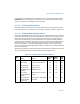
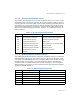
3.1.1.11 Protected Mode Exceptions Section
The “Protected Mode Exceptions” section lists the exceptions that can occur when the
instruction is executed in protected mode and the reasons for the exceptions. Each
exception is given a mnemonic that consists of a pound sign (#) followed by two
letters and an optional error code in parentheses. For example, #GP(0) denotes a
general protection exception with an error code of 0. Table 3-3 associates each two-
letter mnemonic with the corresponding interrupt vector number and exception
name. See Chapter 5, “Interrupt and Exception Handling,” in the Intel® 64 and
IA-32 Architectures Software Developer’s Manual, Volume 3A, for a detailed descrip-
tion of the exceptions.
Application programmers should consult the documentation provided with their oper-
ating systems to determine the actions taken when exceptions occur.
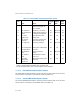
Table 3-3. Intel 64 and IA-32 General Exceptions
Vector
No. Name Source
Protected
Mode
1
Real
Address
Mode
Virtual
8086
Mode
0#DE—Divide ErrorDIV and IDIV instructions. Yes Yes Yes
1 #DB—Debug Any code or data reference. Yes Yes Yes
3 #BP—Breakpoint INT 3 instruction. Yes Yes Yes
4 #OF—Overflow INTO instruction. Yes Yes Yes
5 #BR—BOUND Range
Exceeded
BOUND instruction. Yes Yes Yes
6#UD—Invalid
Opcode (Undefined
Opcode)
UD2 instruction or reserved
opcode.
Yes Yes Yes
7 #NM—Device Not
Available (No Math
Coprocessor)
Floating-point or WAIT/FWAIT
instruction.
Yes Yes Yes