
Intel 64 and IA-32 Architectures Software Developers Manual Volume 3A, System Programming Guide, Part 1


3-40 Vol. 3A
PROTECTED-MODE MEMORY MANAGEMENT
Access (A) and dirty (D) flags (bits 5 and 6) are provided for table entries that point
to pages.
Bits 9, 10, and 11 in all the table entries for the physical address extension are avail-
able for use by software. (When the present flag is clear, bits 1 through 63 are avail-
able to software.) All bits in Figure 3-14 that are marked reserved or 0 should be set
to 0 by software and not accessed by software. When the PSE and/or PAE flags in
control register CR4 are set, the processor generates a page fault (#PF) if reserved
bits in page-directory and page-table entries are not set to 0, and it generates a
general-protection exception (#GP) if reserved bits in a page-directory-pointer-table
entry are not set to 0.
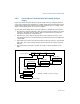
3.9 36-BIT PHYSICAL ADDRESSING USING THE PSE-36
PAGING MECHANISM
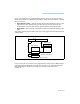
The PSE-36 paging mechanism provides an alternate method (from the PAE mecha-
nism) of extending physical memory addressing to 36 bits. This mechanism uses the
page size extension (PSE) mode and a modified page-directory table to map 4-MByte
pages into a 64-GByte physical address space. As with the PAE mechanism, the
processor provides 4 additional address line pins to accommodate the additional
address bits.
The PSE-36 mechanism was introduced into the IA-32 architecture with the Pentium
III processors. The availability of this feature is indicated with the PSE-36 feature bit
(bit 17 of the EDX register when the CPUID instruction is executed with a source
operand of 1).
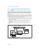
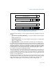
As is shown in Table 3-3, the following flags must be set or cleared to enable the PSE-
36 paging mechanism:
• PSE-36 CPUID feature flag — When set, it indicates the availability of the PSE-
36 paging mechanism on the IA-32 processor on which the CPUID instruction is
executed.
• PG flag (bit 31) in register CR0 — Set to 1 to enable paging.
• PAE flag (bit 5) in control register CR4 — Clear to 0 to disable the PAE paging
mechanism.
• PSE flag (bit 4) in control register CR4 and the PS flag in PDE — Set to 1 to
enable the page size extension for 4-MByte pages.
• Or the PSE flag (bit 4) in control register CR4 — Set to 1 and the PS flag (bit
7) in PDE— Set to 0 to enable 4-KByte pages with 32-bit addressing (below 4
GBytes).