
Intel 64 and IA-32 Architectures Software Developers Manual Volume 3A, System Programming Guide, Part 1


Vol. 3A 3-45
PROTECTED-MODE MEMORY MANAGEMENT
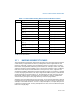
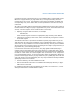
• Page-directory-pointer-table entry — Bits 38:30 provide an offset to an
entry in the page-directory-pointer table. The selected entry provides the base
physical address of a page directory.
• Page-directory entry — Bits 29:21 provide an offset to an entry in the page
directory. The selected entry provides the base physical address of a 2-MByte
page.
• Page offset — Bits 20:0 provides an offset to a physical address in the page.
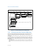
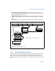
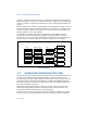
3.10.3 Enhanced Paging Data Structures
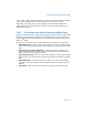
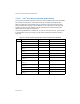
Figure 3-26 shows the format for the PML4 table, page-directory-pointer table,
page-directory and page-table entries when 4-KByte pages are used in IA-32e
mode. Figure 3-27 shows the format for the PML4 table, the page-directory-
pointer table and page-directory entries when 2-MByte pages are used in IA-32e
mode.
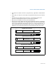
Figure 3-25. IA-32e Mode Paging Structures (2-MByte pages)
Directory Ptr
Linear Address
Dir. Pointer Entry
CR3 (PML4)
39 38
Pointer Table
512 PML4 *512 PDPTE ∗ 512 PDE = 2
27
Pages
9
9
40
1
21
1. 40 bits aligned onto a 4-KByte boundary
19
2-MByte Page
Offset
Physical Addr
Directory Entry
02021
Directory
30 29
Page-Directory-
Page-Directory
PML4
474863
Sign Extended
9
PML4 Entry
NOTE: