
Intel 64 and IA-32 Architectures Software Developers Manual Volume 3A, System Programming Guide, Part 1


Vol. 3A 3-47
PROTECTED-MODE MEMORY MANAGEMENT
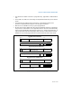
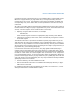
• The maximum number of entries in a page directory, page table, or PML4 table is
512.
• The P, R/W, U/S, PWT, PCD, and A flags are implemented uniformly across all four
levels.
• The base physical address field in each entry is extended to 28 bits if the
processor’s implementation supports a 40-bit physical address.
• Bits 62:52 are available for use by system programmers.
• Bit 63 is the execute-disable bit if the execute-disable bit feature is supported in
the processor. If the feature is not supported, bit 63 is reserved. The functionality
of the execute disable bit is described in Section 4.11, “Page-Level Protection”. It
requires both PAE and enhanced paging data structures. Note that the execute
disable bit can provide page protection in 32-bit PAE mode and IA-32e mode.
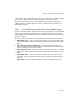
Figure 3-27. Format of Paging Structure Entries for 2-MByte Pages in IA-32e Mode
63 62
32
Reserved (set to 0)
Page-Directory-Pointer-Table Entry*
31
12
11
9
8
543
2
0
P
C
D
P
W
T
Avail
Page-Directory Base Address
Rsvd
63 62 52 51
32
Page Base Address
Reserved (set to 0)
Page-Directory Entry (2-MByte Page)
31 2120 131211 9876543210
P
C
D
P
P
W
T
Page Base Address
G1 A
R
/
W
U
/
S
Avail
P
1
63 62
32
Base Address
Reserved (set to 0)
Page-Map-Level-4-Table Entry*
31
12 11
9
8
543
2
0
P
C
D
P
W
T
AvailPML4 Base Address
Rsvd.
P
1
39
Avail
E
X
B
39
Avail
E
X
B
51
R
/
W
U
/
S
39
Avail
E
X
B
51
6
A
6
A
R
/
W
U
/
S
P
A
T
Reserved (set to 0)
D
Base Address
* Identical to the structures in 4-KByte pages.