
Intel 64 and IA-32 Architectures Software Developers Manual Volume 3A, System Programming Guide, Part 1

5-12 Vol. 3A
INTERRUPT AND EXCEPTION HANDLING
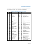
While priority among these classes listed in Table 5-2 is consistent throughout the
architecture, exceptions within each class are implementation-dependent and may
vary from processor to processor. The processor first services a pending exception or
interrupt from the class which has the highest priority, transferring execution to the
first instruction of the handler. Lower priority exceptions are discarded; lower priority
interrupts are held pending. Discarded exceptions are re-generated when the inter-
rupt handler returns execution to the point in the program or task where the excep-
tions and/or interrupts occurred.
5.10 INTERRUPT DESCRIPTOR TABLE (IDT)
The interrupt descriptor table (IDT) associates each exception or interrupt vector
with a gate descriptor for the procedure or task used to service the associated excep-
tion or interrupt. Like the GDT and LDTs, the IDT is an array of 8-byte descriptors (in
protected mode). Unlike the GDT, the first entry of the IDT may contain a descriptor.
To form an index into the IDT, the processor scales the exception or interrupt vector
by eight (the number of bytes in a gate descriptor). Because there are only 256 inter-
rupt or exception vectors, the IDT need not contain more than 256 descriptors. It can
contain fewer than 256 descriptors, because descriptors are required only for the
interrupt and exception vectors that may occur. All empty descriptor slots in the IDT
should have the present flag for the descriptor set to 0.
The base addresses of the IDT should be aligned on an 8-byte boundary to maximize
performance of cache line fills. The limit value is expressed in bytes and is added to
the base address to get the address of the last valid byte. A limit value of 0 results in
exactly 1 valid byte. Because IDT entries are always eight bytes long, the limit should
always be one less than an integral multiple of eight (that is, 8N – 1).
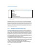
The IDT may reside anywhere in the linear address space. As shown in Figure 5-1,
the processor locates the IDT using the IDTR register. This register holds both a
32-bit base address and 16-bit limit for the IDT.
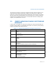
10 (Lowest) Faults on Executing an Instruction
- Overflow
- Bound error
- Invalid TSS
- Segment Not Present
- Stack fault
- General Protection
- Data Page Fault
- Alignment Check
- x87 FPU Floating-point exception
- SIMD floating-point exception
NOTE:
1. The Intel486
TM
processor and earlier processors group nonmaskable and maskable interrupts in
the same priority class.
Table 5-2. Priority Among Simultaneous Exceptions and Interrupts (Contd.)