
Intel 64 and IA-32 Architectures Software Developers Manual Volume 3A, System Programming Guide, Part 1

5-24 Vol. 3A
INTERRUPT AND EXCEPTION HANDLING
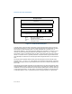
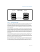
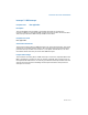
In 64-bit mode, the IDT index is formed by scaling the interrupt vector by 16. The
first eight bytes (bytes 7:0) of a 64-bit mode interrupt gate are similar but not iden-
tical to legacy 32-bit interrupt gates. The type field (bits 11:8 in bytes 7:4) is
described in Table 3-2. The Interrupt Stack Table (IST) field (bits 4:0 in bytes 7:4) is
used by the stack switching mechanisms described in Section 5.14.5, “Interrupt
Stack Table.” Bytes 11:8 hold the upper 32 bits of the target RIP (interrupt segment
offset) in canonical form. A general-protection exception (#GP) is generated if soft-
ware attempts to reference an interrupt gate with a target RIP that is not in canonical
form.
The target code segment referenced by the interrupt gate must be a 64-bit code
segment (CS.L = 1, CS.D = 0). If the target is not a 64-bit code segment, a general-
protection exception (#GP) is generated with the IDT vector number reported as the
error code.
Only 64-bit interrupt and trap gates can be referenced in IA-32e mode (64-bit mode
and compatibility mode). Legacy 32-bit interrupt or trap gate types (0EH or 0FH) are
redefined in IA-32e mode as 64-bit interrupt and trap gate types. No 32-bit interrupt
or trap gate type exists in IA-32e mode. If a reference is made to a 16-bit interrupt
or trap gate (06H or 07H), a general-protection exception (#GP(0)) is generated.
Figure 5-7. 64-Bit IDT Gate Descriptors
31
16
15
13
14 12
8
7
0
P
Offset 31..16
D
P
L
0
4
31
16
15
0
Segment Selector
Offset 15..0
0
TYPE
Interrupt/Trap Gate
DPL
Offset
P
Selector
Descriptor Privilege Level
Offset to procedure entry point
Segment Present flag
Segment Selector for destination code segment
45
0 0 0
31
0
Offset 63..32
8
31
0
12
11
IST
0
0
2
Reserved
IST
Interrupt Stack Table