
Intel 64 and IA-32 Architectures Software Developers Manual Volume 3A, System Programming Guide, Part 1

6-20 Vol. 3A
TASK MANAGEMENT
page directory for each task. Because the PDBR (control register CR3) is loaded
on task switches, each task may have a different page directory.
The linear address spaces of different tasks may map to completely distinct physical
addresses. If the entries of different page directories point to different page tables
and the page tables point to different pages of physical memory, then the tasks do
not share physical addresses.
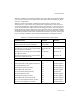
With either method of mapping task linear address spaces, the TSSs for all tasks
must lie in a shared area of the physical space, which is accessible to all tasks. This
mapping is required so that the mapping of TSS addresses does not change while the
processor is reading and updating the TSSs during a task switch. The linear address
space mapped by the GDT also should be mapped to a shared area of the physical
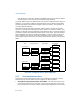
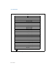
space; otherwise, the purpose of the GDT is defeated. Figure 6-9 shows how the
linear address spaces of two tasks can overlap in the physical space by sharing page
tables.
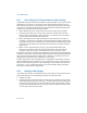
6.5.2 Task Logical Address Space
To allow the sharing of data among tasks, use the following techniques to create
shared logical-to-physical address-space mappings for data segments:
• Through the segment descriptors in the GDT — All tasks must have access
to the segment descriptors in the GDT. If some segment descriptors in the GDT
point to segments in the linear-address space that are mapped into an area of the
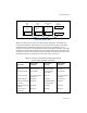
Figure 6-9. Overlapping Linear-to-Physical Mappings
Task A
TSS
PDE
Page Directories
PDE
PTE
PTE
PTE
PTE
PTE
Page Tables
Page Frames
Task A
Task A
Shared
Shared
Task B
Task B
Shared PT
PTE
PTE
PDE
PDE
PDBR
PDBR
Task A TSS
Task B TSS