
Intel 64 and IA-32 Architectures Software Developers Manual Volume 3A, System Programming Guide, Part 1

8-6 Vol. 3A
ADVANCED PROGRAMMABLE INTERRUPT CONTROLLER (APIC)
8.4 LOCAL APIC
The following sections describe the architecture of the local APIC and how to detect
it, identify it, and determine its status. Descriptions of how to program the local APIC
are given in Section 8.5.1, “Local Vector Table,” and Section 8.6.1, “Interrupt
Command Register (ICR).”
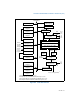
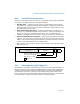
8.4.1 The Local APIC Block Diagram
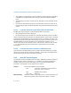
Figure 8-4 gives a functional block diagram for the local APIC. Software interacts with
the local APIC by reading and writing its registers. APIC registers are memory-
mapped to a 4-KByte region of the processor’s physical address space with an initial
starting address of FEE00000H. For correct APIC operation, this address space must
be mapped to an area of memory that has been designated as strong uncacheable
(UC). See Section 10.3, “Methods of Caching Available.”
In MP system configurations, the APIC registers for Intel 64 or IA-32 processors on
the system bus are initially mapped to the same 4-KByte region of the physical
address space. Software has the option of changing initial mapping to a different
4-KByte region for all the local APICs or of mapping the APIC registers for each local
APIC to its own 4-KByte region. Section 8.4.5, “Relocating the Local APIC Registers,”
describes how to relocate the base address for APIC registers.
NOTE
For P6 family, Pentium 4, and Intel Xeon processors, the APIC
handles all memory accesses to addresses within the 4-KByte APIC
register space internally and no external bus cycles are produced. For
the Pentium processors with an on-chip APIC, bus cycles are
produced for accesses to the APIC register space. Thus, for software
intended to run on Pentium processors, system software should
explicitly not map the APIC register space to regular system memory.
Doing so can result in an invalid opcode exception (#UD) being
generated or unpredictable execution.