
Intel 64 and IA-32 Architectures Software Developers Manual Volume 3A, System Programming Guide, Part 1

8-30 Vol. 3A
ADVANCED PROGRAMMABLE INTERRUPT CONTROLLER (APIC)
How the ICR, LDR, and DFR are used to select an IPI destination depends on the
destination mode used: physical, logical, broadcast/self, or lowest-priority delivery
mode. These destination modes are described in the following sections.
8.6.2.1 Physical Destination Mode
In physical destination mode, the destination processor is specified by its local APIC
ID (see Section 8.4.6, “Local APIC ID”). For Pentium 4 and Intel Xeon processors,
either a single destination (local APIC IDs 00H through FEH) or a broadcast to all
APICs (the APIC ID is FFH) may be specified in physical destination mode.
A broadcast IPI (bits 28-31 of the MDA are 1's) or I/O subsystem initiated interrupt
with lowest priority delivery mode is not supported in physical destination mode and
must not be configured by software. Also, for any non-broadcast IPI or I/O
subsystem initiated interrupt with lowest priority delivery mode, software must
ensure that APICs defined in the interrupt address are present and enabled to receive
interrupts.
For the P6 family and Pentium processors, a single destination is specified in physical
destination mode with a local APIC ID of 0H through 0EH, allowing up to 15 local
APICs to be addressed on the APIC bus. A broadcast to all local APICs is specified with
0FH.
NOTE
The number of local APICs that can be addressed on the system bus
may be restricted by hardware.
8.6.2.2 Logical Destination Mode
In logical destination mode, IPI destination is specified using an 8-bit message desti-
nation address (MDA), which is entered in the destination field of the ICR. Upon
receiving an IPI message that was sent using logical destination mode, a local APIC
compares the MDA in the message with the values in its LDR and DFR to determine if
it should accept and handle the IPI. For both configurations of logical destination
mode, when combined with lowest priority delivery mode, software is responsible for
ensuring that all of the local APICs included in or addressed by the IPI or I/O
subsystem interrupt are present and enabled to receive the interrupt.
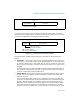
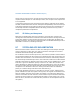
Figure 8-13 shows the layout of the logical destination register (LDR). The 8-bit
logical APIC ID field in this register is used to create an identifier that can be
compared with the MDA.
NOTE
The logical APIC ID should not be confused with the local APIC ID that
is contained in the local APIC ID register.