
Intel 64 and IA-32 Architectures Software Developers Manual Volume 3A, System Programming Guide, Part 1

Vol. 3A 8-31
ADVANCED PROGRAMMABLE INTERRUPT CONTROLLER (APIC)
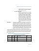
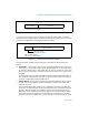
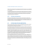
Figure 8-14 shows the layout of the destination format register (DFR). The 4-bit
model field in this register selects one of two models (flat or cluster) that can be used
to interpret the MDA when using logical destination mode.
The interpretation of MDA for the two models is described in the following para-
graphs.
1. Flat Model — This model is selected by programming DFR bits 28 through 31 to
1111. Here, a unique logical APIC ID can be established for up to 8 local APICs
by setting a different bit in the logical APIC ID field of the LDR for each local
APIC. A group of local APICs can then be selected by setting one or more bits in
the MDA.
Each local APIC performs a bit-wise AND of the MDA and its logical APIC ID. If a
true condition is detected, the local APIC accepts the IPI message. A broadcast to
all APICs is achieved by setting the MDA to 1s.
2. Cluster Model — This model is selected by programming DFR bits 28 through 31
to 0000. This model supports two basic destination schemes: flat cluster and
hierarchical cluster.
The flat cluster destination model is only supported for P6 family and Pentium
processors. Using this model, all APICs are assumed to be connected through the
APIC bus. Bits 28 through 31 of the MDA contains the encoded address of the
destination cluster and bits 24 through 27 identify up to four local APICs within
the cluster (each bit is assigned to one local APIC in the cluster, as in the flat
connection model). To identify one or more local APICs, bits 28 through 31 of the
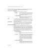
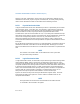
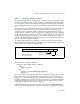
Figure 8-13. Logical Destination Register (LDR)
Figure 8-14. Destination Format Register (DFR)
31
0
2324
ReservedLogical APIC ID
Address: 0FEE0 00D0H
Value after reset: 0000 0000H
31
0
Model
28
Reserved (All 1s)
Address: 0FEE0 00E0H
Value after reset: FFFF FFFFH
Flat model: 1111B
Cluster model: 0000B