
Intel 64 and IA-32 Architectures Software Developers Manual Volume 3A, System Programming Guide, Part 1


Vol. 3A 8-47
ADVANCED PROGRAMMABLE INTERRUPT CONTROLLER (APIC)
8.11.1 Message Address Register Format
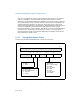
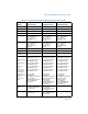
The format of the Message Address Register (lower 32-bits) is shown in Figure 8-24.
Fields in the Message Address Register are as follows:
1. Bits 31-20 — These bits contain a fixed value for interrupt messages (0FEEH).
This value locates interrupts at the 1-MByte area with a base address of 4G –
18M. All accesses to this region are directed as interrupt messages. Care must
to be taken to ensure that no other device claims the region as I/O space.
2. Destination ID — This field contains an 8-bit destination ID. It identifies the
message’s target processor(s). The destination ID corresponds to bits 63:56 of
the I/O APIC Redirection Table Entry if the IOAPIC is used to dispatch the
interrupt to the processor(s).
3. Redirection hint indication (RH) — This bit indicates whether the message
should be directed to the processor with the lowest interrupt priority among
processors that can receive the interrupt.
• When RH is 0, the interrupt is directed to the processor listed in the
Destination ID field.
• When RH is 1 and the physical destination mode is used, the Destination
ID field must not be set to 0xFF; it must point to a processor that is
present and enabled to receive the interrupt.
• When RH is 1 and the logical destination mode is active in a system using
a flat addressing model, the Destination ID field must be set so that bits
set to 1 identify processors that are present and enabled to receive the
interrupt.
• If RH is set to 1 and the logical destination mode is active in a system
using cluster addressing model, then Destination ID field must not be set
to 0xFF; the processors identified with this field must be present and
enabled to receive the interrupt.
4. Destination mode (DM) — This bit indicates whether the Destination ID field
should be interpreted as logical or physical APIC ID for delivery of the lowest
priority interrupt. If RH is 1 and DM is 0, the Destination ID field is in physical
destination mode and only the processor in the system that has the matching
Figure 8-24. Layout of the MSI Message Address Register
31 20 19 12 11 4 3 2 1 0
0FEEH Destination ID Reserved RH DM XX