
Intel 64 and IA-32 Architectures Software Developers Manual Volume 3A, System Programming Guide, Part 1

Vol. 3A 10-17
MEMORY CACHE CONTROL
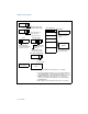
enabled and the CD flag in control register CR0 is clear. The PCD flag enables
caching of the page table or page when clear and prevents caching when set.
• PWT flag in the page-directory and page-table entries — Controls the write
policy for individual page tables and pages, respectively (see Section 3.7.6,
“Page-Directory and Page-Table Entries”). This flag only has effect when paging is
enabled and the NW flag in control register CR0 is clear. The PWT flag enables
write-back caching of the page table or page when clear and write-through
caching when set.
• PCD and PWT flags in control register CR3 — Control the global caching and
write policy for the page directory (see Section 2.5, “Control Registers”). The PCD
flag enables caching of the page directory when clear and prevents caching when
set. The PWT flag enables write-back caching of the page directory when clear
and write-through caching when set. These flags do not affect the caching and
write policy for individual page tables. These flags only have effect when paging
is enabled and the CD flag in control register CR0 is clear.
• G (global) flag in the page-directory and page-table entries (introduced
to the IA-32 architecture in the P6 family processors) — Controls the
flushing of TLB entries for individual pages. See Section 3.12, “Translation
Lookaside Buffers (TLBs),” for more information about this flag.
• PGE (page global enable) flag in control register CR4 — Enables the estab-
lishment of global pages with the G flag. See Section 3.12, “Translation Lookaside
Buffers (TLBs),” for more information about this flag.
• Memory type range registers (MTRRs) (introduced in P6 family
processors) — Control the type of caching used in specific regions of physical
memory. Any of the caching types described in Section 10.3, “Methods of Caching
Available,” can be selected. See Section 10.11, “Memory Type Range Registers
(MTRRs),” for a detailed description of the MTRRs.
• Page Attribute Table (PAT) MSR (introduced in the Pentium III processor)
— Extends the memory typing capabilities of the processor to permit memory
types to be assigned on a page-by-page basis (see Section 10.12, “Page Attribute
Table (PAT)”).
• Third-Level Cache Disable flag, bit 6 of the IA32_MISC_ENABLE MSR
(introduced in the Intel Xeon processors) — Allows the L3 cache to be
disabled and enabled, independently of the L1 and L2 caches.
• KEN# and WB/WT# pins (Pentium processor) — Allow external hardware to
control the caching method used for specific areas of memory. They perform
similar (but not identical) functions to the MTRRs in the P6 family processors.
• PCD and PWT pins (Pentium processor) — These pins (which are associated
with the PCD and PWT flags in control register CR3 and in the page-directory and
page-table entries) permit caching in an external L2 cache to be controlled on a
page-by-page basis, consistent with the control exercised on the L1 cache of
these processors. The P6 and more recent processor families do not provide
these pins because the L2 cache in internal to the chip package.