
Intel 64 and IA-32 Architectures Software Developers Manual Volume 3A, System Programming Guide, Part 1

Vol. 3A 10-33
MEMORY CACHE CONTROL
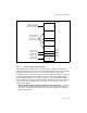
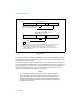
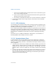
Figure 10-6 shows flags and fields in these registers. The functions of these flags and
fields are:
• Type field, bits 0 through 7 — Specifies the memory type for the range (see
Table 10-8 for the encoding of this field).
• PhysBase field, bits 12 through (MAXPHYADDR-1) — Specifies the base
address of the address range. This 24-bit value, in the case where MAXPHYADDR
is 36 bits, is extended by 12 bits at the low end to form the base address (this
automatically aligns the address on a 4-KByte boundary).
• PhysMask field, bits 12 through (MAXPHYADDR-1) — Specifies a mask (24
bits if the maximum physical address size is 36 bits, 28 bits if the maximum
physical address size is 40 bits). The mask determines the range of the region
being mapped, according to the following relationships:
— Address_Within_Range AND PhysMask = PhysBase AND PhysMask
— This value is extended by 12 bits at the low end to form the mask value. For
more information: see Section 10.11.3, “Example Base and Mask Calcula-
tions.”
— The width of the PhysMask field depends on the maximum physical address
size supported by the processor.
CPUID.80000008H reports the maximum physical address size supported by
the processor. If CPUID.80000008H is not available, software may assume
that the processor supports a 36-bit physical address size (then PhysMask is
24 bits wide and the upper 28 bits of IA32_MTRR_PHYSMASKn are reserved).
See the Note below.
• V (valid) flag, bit 11 — Enables the register pair when set; disables register
pair when clear.