
Intel 64 and IA-32 Architectures Software Developers Manual Volume 3A, System Programming Guide, Part 1

10-34 Vol. 3A
MEMORY CACHE CONTROL
All other bits in the IA32_MTRR_PHYSBASEn and IA32_MTRR_PHYSMASKn registers
are reserved; the processor generates a general-protection exception (#GP) if soft-
ware attempts to write to them.
Some mask values can result in ranges that are not continuous. In such ranges, the
area not mapped by the mask value is set to the default memory type. Intel does not
encourage the use of “discontinuous” ranges because they could require physical
memory to be present throughout the entire 4-GByte physical memory map. If
memory is not provided, the behaviour is undefined.
NOTE
It is possible for software to parse the memory descriptions that
BIOS provides by using the ACPI/INT15 e820 interface mechanism.
This information then can be used to determine how MTRRs are
initialized (for example: allowing the BIOS to define valid memory
ranges and the maximum memory range supported by the platform,
including the processor).
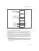
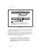
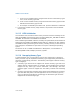
Figure 10-6. IA32_MTRR_PHYSBASEn and IA32_MTRR_PHYSMASKn Variable-Range
Register Pair
V — Valid
PhysMask — Sets range mask
IA32_MTRR_PHYSMASKn Register
63
0
Reserved
101112
V
Reserved
MAXPHYADDR
PhysMask
Type — Memory type for range
PhysBase — Base address of range
IA32_MTRR_PHYSBASEn Register
63
0
Reserved
1112
Type
MAXPHYADDR
PhysBase
78
Reserved
MAXPHYADDR: The bit position indicated by MAXPHYADDR depends on the maximum
physical address range supported by the processor. It is reported by CPUID leaf
function 80000008H. If CPUID does not support leaf 80000008H, the processor
supports 36-bit physical address size, then bit PhysMask consists of bits 35:12, and
bits 63:36 are reserved.