
Intel 64 and IA-32 Architectures Software Developers Manual Volume 3A, System Programming Guide, Part 1

13-10 Vol. 3A
POWER AND THERMAL MANAGEMENT
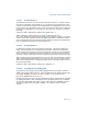
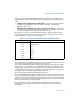
• High-Temperature Interrupt Enable flag, bit 0 — Enables an interrupt to be
generated on the transition from a low-temperature to a high-temperature when
set; disables the interrupt when clear.(R/W).
• Low-Temperature Interrupt Enable flag, bit 1 — Enables an interrupt to be
generated on the transition from a high-temperature to a low-temperature when
set; disables the interrupt when clear.
The thermal monitor interrupt can be masked by the thermal LVT entry. After a
power-up or reset, the low-temperature interrupt enable and high-temperature
interrupt enable flags in the IA32_THERM_INTERRUPT MSR are cleared (interrupts
are disabled) and the thermal LVT entry is set to mask interrupts. This interrupt
should be handled either by the operating system or system management mode
(SMM) code.
Note that the operation of the thermal monitoring mechanism has no effect upon the
clock rate of the processor's internal high-resolution timer (time stamp counter).
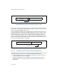
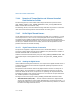
13.4.3 Software Controlled Clock Modulation
Pentium 4, Intel Xeon and Pentium M processors also support software-controlled
clock modulation. This provides a means for operating systems to implement a power
management policy to reduce the power consumption of the processor. Here, the
stop-clock duty cycle is controlled by software through the
IA32_CLOCK_MODULATION MSR (see Figure 13-7).
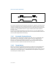
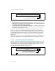
Figure 13-6. IA32_THERM_INTERRUPT MSR
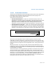
Figure 13-7. IA32_CLOCK_MODULATION MSR
63 0
Reserved
12
High-Temperature Interrupt Enable
Low-Temperature Interrupt Enable
63 0
Reserved
13
On-Demand Clock Modulation Duty Cycle
On-Demand Clock Modulation Enable
45
Reserved