
Intel 64 and IA-32 Architectures Software Developers Manual Volume 3A, System Programming Guide, Part 1


14-20 Vol. 3A
MACHINE-CHECK ARCHITECTURE
14.7.2.5 Bus and Interconnect Errors
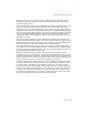
The bus and interconnect errors are defined with the 2-bit PP (participation), 1-bit T
(time-out), and 2-bit II (memory or I/O) sub-fields, in addition to the LL and RRRR
sub-fields (see Table 14-10). The bus error conditions are implementation dependent
and related to the type of bus implemented by the processor. Likewise, the intercon-
nect error conditions are predicated on a specific implementation-dependent inter-
connect model that describes the connections between the different levels of the
storage hierarchy. The type of bus is implementation dependent, and as such is not
specified in this document. A bus or interconnect transaction consists of a request
involving an address and a response.
14.7.3 Machine-Check Error Codes Interpretation
Appendix E, “Interpreting Machine-Check Error Codes,” provides information on
interpreting the MCA error code, model-specific error code, and other information
error code fields. For P6 family processors, information has been included on
decoding external bus errors. For Pentium 4 and Intel Xeon processors; information
is included on external bus, internal timer and memory hierarchy errors.
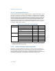
Table 14-10. Encodings of PP, T, and II Sub-Fields
Sub-Field Transaction Mnemonic Binary Encoding
PP (Participation) Local processor
1
originated request SRC 00
Local processor
1
responded to request RES 01
Local processor
1
observed error as
third party
OBS 10
Generic 11
T (Time-out) Request timed out TIMEOUT 1
Request did not time out NOTIMEOUT 0
II (Memory or I/O) Memory Access M 00
Reserved 01
I/O IO 10
Other transaction 11
NOTE:
1. Local processor differentiates the processor reporting the error from other system components
(including the APIC, other processors, etc.).