
Intel 64 and IA-32 Architectures Software Developers Manual Volume 3A, System Programming Guide, Part 1

Vol. 3A 15-7
8086 EMULATION
An IRET instruction at the end of the handler procedure reverses these steps to
return program control to the interrupted program. Exceptions do not return error
codes in real-address mode.
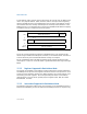
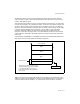
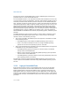
The interrupt vector table is an array of 4-byte entries (see Figure 15-2). Each entry
consists of a far pointer to a handler procedure, made up of a segment selector and
an offset. The processor scales the interrupt or exception vector by 4 to obtain an
offset into the interrupt table. Following reset, the base of the interrupt vector table
is located at physical address 0 and its limit is set to 3FFH. In the Intel 8086
processor, the base address and limit of the interrupt vector table cannot be
changed. In the later IA-32 processors, the base address and limit of the interrupt
vector table are contained in the IDTR register and can be changed using the LIDT
instruction.
(For backward compatibility to Intel 8086 processors, the default base address and
limit of the interrupt vector table should not be changed.)
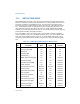
Table 15-1 shows the interrupt and exception vectors that can be generated in real-
address mode and virtual-8086 mode, and in the Intel 8086 processor. See Chapter 5,
“Interrupt and Exception Handling”, for a description of the exception conditions.
Figure 15-2. Interrupt Vector Table in Real-Address Mode
0
2
4
8
12
0
15
Segment Selector
Offset
* Interrupt vector number 0 selects entry 0
Interrupt Vector 0*
Entry 1
Entry 2
Entry 3
Up to Entry 255
IDTR
(called “interrupt vector 0”) in the interrupt
vector table. Interrupt vector 0 in turn
points to the start of the interrupt handler
for interrupt 0.