
Intel 64 and IA-32 Architectures Software Developers Manual Volume 3A, System Programming Guide, Part 1

2-20 Vol. 3A
SYSTEM ARCHITECTURE OVERVIEW
See also: Section 10.5.3, “Preventing Caching,” and Section 10.5, “Cache
Control.”
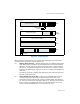
NW Not Write-through (bit 29 of CR0) — When the NW and CD flags are
clear, write-back (for Pentium 4, Intel Xeon, P6 family, and Pentium proces-
sors) or write-through (for Intel486 processors) is enabled for writes that hit
the cache and invalidation cycles are enabled. See Table 10-5 for detailed
information about the affect of the NW flag on caching for other settings of
the CD and NW flags.
AM Alignment Mask (bit 18 of CR0) — Enables automatic alignment checking
when set; disables alignment checking when clear. Alignment checking is
performed only when the AM flag is set, the AC flag in the EFLAGS register is
set, CPL is 3, and the processor is operating in either protected or virtual-
8086 mode.
WP Write Protect (bit 16 of CR0) — Inhibits supervisor-level procedures from
writing into user-level read-only pages when set; allows supervisor-level
procedures to write into user-level read-only pages when clear (regardless of
the U/S bit setting; see Section 3.7.6). This flag facilitates implementation of
the copy-on-write method of creating a new process (forking) used by oper-
ating systems such as UNIX.
NE Numeric Error (bit 5 of CR0) — Enables the native (internal) mechanism
for reporting x87 FPU errors when set; enables the PC-style x87 FPU error
reporting mechanism when clear. When the NE flag is clear and the IGNNE#
input is asserted, x87 FPU errors are ignored. When the NE flag is clear and
the IGNNE# input is deasserted, an unmasked x87 FPU error causes the
processor to assert the FERR# pin to generate an external interrupt and to
stop instruction execution immediately before executing the next waiting
floating-point instruction or WAIT/FWAIT instruction.
The FERR# pin is intended to drive an input to an external interrupt
controller (the FERR# pin emulates the ERROR# pin of the Intel 287 and
Intel 387 DX math coprocessors). The NE flag, IGNNE# pin, and FERR# pin
are used with external logic to implement PC-style error reporting.
See also: “Software Exception Handling” in Chapter 8, “Programming with
the x87 FPU,” and Appendix A, “Eflags Cross-Reference,” in the Intel® 64
and IA-32 Architectures Software Developer’s Manual, Volume 1.
ET Extension Type (bit 4 of CR0) — Reserved in the Pentium 4, Intel Xeon, P6
family, and Pentium processors. In the Pentium 4, Intel Xeon, and P6 family
processors, this flag is hardcoded to 1. In the Intel386 and Intel486 proces-
sors, this flag indicates support of Intel 387 DX math coprocessor instruc-
tions when set.
TS Task Switched (bit 3 of CR0) — Allows the saving of the x87
FPU/MMX/SSE/SSE2/ SSE3 context on a task switch to be delayed until an
x87 FPU/MMX/SSE/SSE2/SSE3 instruction is actually executed by the new
task. The processor sets this flag on every task switch and tests it when
executing x87 FPU/MMX/SSE/SSE2/SSE3 instructions.