
Intel 64 and IA-32 Architectures Software Developers Manual Volume 3A, System Programming Guide, Part 1

2-22 Vol. 3A
SYSTEM ARCHITECTURE OVERVIEW
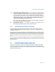
clear. This flag also affects the execution of MMX/SSE/SSE2/SSE3 instruc-
tions.
When the EM flag is set, execution of an x87 FPU instruction generates a
device-not-available exception (#NM). This flag must be set when the
processor does not have an internal x87 FPU or is not connected to an
external math coprocessor. Setting this flag forces all floating-point instruc-
tions to be handled by software emulation. Table 9-2 shows the recom-
mended setting of this flag, depending on the IA-32 processor and x87 FPU
or math coprocessor present in the system. Table 2-1 shows the interaction
of the EM, MP, and TS flags.
Also, when the EM flag is set, execution of an MMX instruction causes an
invalid-opcode exception (#UD) to be generated (see Table 11-1). Thus, if an
IA-32 or Intel 64 processor incorporates MMX technology, the EM flag must
be set to 0 to enable execution of MMX instructions.
Similarly for SSE/SSE2/SSE3/SSSE3 extensions, when the EM flag is set,
execution of most SSE/SSE2/SSE3/SSSE3 instructions causes an invalid
opcode exception (#UD) to be generated (see Table 12-1). If an IA-32 or
Intel 64 processor incorporates the SSE/SSE2/SSE3/SSSE3 extensions, the
EM flag must be set to 0 to enable execution of these extensions.
SSE/SSE2/SSE3 instructions not affected by the EM flag include: PAUSE,
PREFETCHh, SFENCE, LFENCE, MFENCE, MOVNTI, and CLFLUSH.
MP Monitor Coprocessor (bit 1 of CR0). — Controls the interaction of the
WAIT (or FWAIT) instruction with the TS flag (bit 3 of CR0). If the MP flag is
set, a WAIT instruction generates a device-not-available exception (#NM) if
the TS flag is also set. If the MP flag is clear, the WAIT instruction ignores the
setting of the TS flag. Table 9-2 shows the recommended setting of this flag,
depending on the IA-32 processor and x87 FPU or math coprocessor present
in the system. Table 2-1 shows the interaction of the MP, EM, and TS flags.
PE Protection Enable (bit 0 of CR0) — Enables protected mode when set;
enables real-address mode when clear. This flag does not enable paging
directly. It only enables segment-level protection. To enable paging, both the
PE and PG flags must be set.
See also: Section 9.9, “Mode Switching.”
PCD Page-level Cache Disable (bit 4 of CR3) — Controls caching of the
current page directory. When the PCD flag is set, caching of the page-direc-
tory is prevented; when the flag is clear, the page-directory can be cached.
This flag affects only the processor’s internal caches (both L1 and L2, when
present). The processor ignores this flag if paging is not used (the PG flag in
register CR0 is clear) or the CD (cache disable) flag in CR0 is set.
See also: Chapter 10, “Memory Cache Control” (for more about the use of
the PCD flag) and Section 3.7.6, “Page-Directory and Page-Table Entries” (for
a description of a companion PCD flag in page-directory and page-table
entries).