
Intel Pentium 4 Processor 423 Pin Socket (PGA423) Design Guidelines


®
423 Pin Socket Design Guidelines
23
In
Out
Package
Socket
Motherboard
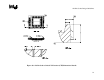
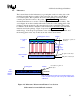
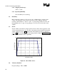
Figure 12: Methodology for Measuring Total Electrical Resistance
In
Out
Package
Motherboard
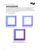
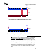
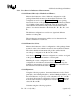
Figure 13: Methodology for Measuring Electrical Resistance of the Jumper
Determination of Average Electrical Resistance:
Figure 12 and Figure 13 show the proposed methodology for measuring the
final electrical resistance. The methodology requires measuring package
fixtures flush-mounted directly to the motherboard fixtures, so that the pin
shoulder is flush with the motherboard, to get the averaged jumper resistance,
Rjumper. All measurement should be taken from the solder tail side of the
board. The Rjumper should come from a good statistical average of many
package fixtures flush mounted to a motherboard fixture. For each chain, one
measurement per chain will be taken; there are 3 chains per board. The same
measurements are then made with a package fixture mounted on a vendor’s
socket, and both are mounted on a motherboard fixture; this provides the
Rtotal.