
Intel Pentium 4 Processor 423 Pin Socket (PGA423) Design Guidelines


®
423 Pin Socket Design Guidelines
27
4.2.1. Procedure for Inductance Measurements:
4.2.1.1. Mounted Directly to Motherboard Fixture:
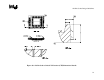
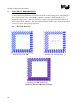
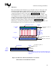
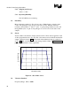
Measure the inductance of the 4 different configurations of the
package fixture flush-mounted to the motherboard fixture. The
configurations can be seen in Figure 16. This will force spacing
between the bottom of the package and top of the motherboard fixture
to be 0.010in, which matches the height of the pin shoulder. The
values that this measurement will produce will be labeled with a
prime to note the fact that this is the fixture; R
1
’, R
2
’, R
2a
’, R
4
’, and
R
s
’.
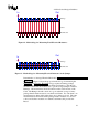
The different configurations consider one signal and different
numbers of return paths.
These inductance measurements will be used to characterize the
fixture contribution for each case.
4.2.1.2. Mounted to Socket:
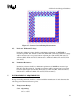
Measure the inductance of the 4 configurations of the package fixture
mounted on the socket, which is mounted to the motherboard fixture.
The values that this measurement will produce will be labeled
according to configuration: R
1
, R
2
, R
2a
, R
4
, and R
s
.
As in Section 4.2.1.1, the different configurations consider one signal
as the ground and different numbers of return paths.
Matching the correct configuration in Section 4.2.1.1with the
configurations of inductance measurements taken in this step, the
inductance measurements of Section 4.2.1.1will be subtracted from
the inductance measurements taken in this step.
4.2.1.3. Equations:
Using the following equations, the mutual inductance for the 71mil-
pitch (M
71
), the 142mil-pitch (M
142
), and the 100mil-pitch (M
100
); and
the self-inductance of a pin (L
s
) can be calculated. R
1
’, R
2
’, and R
4
’
come from the measured configurations in Section 4.2.1.2subtracted
from the same measured configurations in Section 4.2.1.1, with the
values R
1
, R
2
, and R
4
.
Calculate using the following equations:
R
1
– R
1
’ = 2*(L
s
-M
71
) (equation 5)