
Intel Pentium 4 Processor 423 Pin Socket (PGA423) Design Guidelines


423 Pin Socket Design Guidelines
®
28
R
2
– R
2
’ = (3*L
s
/2 – 2*M
71
) + M
100
/2 (equation 6)
R
4
– R
4
’ = 5*L
s
/4 – 2* M
71
+ M
100
/2 + M
142
/4 (equation 7)
R
s
– R
s
’ = 3*L
s
/2 – 2* M
142
+ 0.5M
280
(equation 8)
*note: M
280
is the mutual at 280mils away. Since that value is small and we
only use half of that value, we will neglect it for equation 8.
4.2.2. Loop Inductance:
To qualify, the socket must meet the loop inductance (L
Loop
) as shown in
equation 9.
L
Loop
= 2 * (L
S
– M) (equation 9)
M refers to the closest adjacent mutual inductance term at the 71-mil pitch
The loop inductance from the calculation in equation 9, using this
methodology, shall not exceed 4.3nH at 1GHz.
4.3. Pin-to-Pin Capacitance:
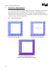
Pin-to-pin capacitance shall be measured using configuration R
1
, with the
motherboard not connected and only the measurements with the same test vehicle
mounted on the socket will be taken. Capacitance for the two pins shall not exceed
1.0 pF at 400MHz.
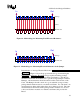
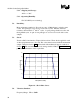
4.4. Contact Current Rating:
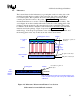
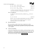
Contact current rating shall be tested at 1.0A/pin. At this current rating, record the
temperature rise. Testing shall be measured per EIA 364, Test Procedure 70A. The
power supply is connected between B2 and AN3 and the input voltage needs to be
adjusted to draw 1A through the daisy chain. The temperature is measured at Y4.
This measurement technique is detailed in Figure 17.