
Intel Pentium 4 Processor on 90 nm Process


70 Datasheet
Thermal Specifications and Design Considerations
§
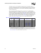
Table 28. Thermal Diode Parameters
Symbol Parameter Min Typ Max Unit Notes
I
FW
Forward Bias Current 11 187 uA
1
NOTES:
1. Intel does not support or recommend operation of the thermal diode under reverse bias.
n Diode Ideality Factor 1.0083 1.011 1.023
2, 3, 4, 5
2. Characterized at 75 °C.
3. Not 100% tested. Specified by design characterization.
4. The ideality factor, n, represents the deviation from ideal diode behavior as exemplified by the diode equa-
tion:
I
FW
= I
S
* (e
qV
D
/nkT
–1)
where I
S
= saturation current, q = electronic charge, V
D
= voltage across the diode, k = Boltzmann
Constant, and T = absolute temperature (Kelvin).
5. Devices found to have an ideality factor of 1.0183 to 1.023 will create a temperature error of approximately
2 C higher than the actual temperature. In order to minimize any potential acoustic impact of this temperature
error, Tcontrol will be increased by 2 C on these parts.
R
T
Series Resistance 3.242 3.33 3.594 Ω
2, 3, 6
6. The series resistance, R
T
, is provided to allow for a more accurate measurement of the thermal diode tem-
perature. R
T
, as defined, includes the pins of the processor but does not include any socket resistance or
board trace resistance between the socket and the external remote diode thermal sensor. RT can be used
by remote diode thermal sensors with automatic series resistance cancellation to calibrate out this error term.
Another application is that a temperature offset can be manually calculated and programmed into an offset
register in the remote diode thermal sensors as exemplified by the equation:
T
error
= [R
T
* (N-1) * I
FWmin
] / [nk/q * ln N]
where T
error
= sensor temperature error, N = sensor current ratio, k = Boltzmann Constant, q = electronic
charge.
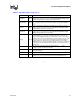
Table 29. Thermal Diode Interface
Pin Name Pin Number Pin Description
THERMDA B3 diode anode
THERMDC C4 diode cathode