
Assembling Intel Reference Components for the Intel Pentium 4 Processor in 478-Pin Package


6
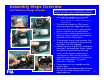
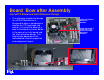
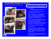
Assembly Steps Overview
Intel Reference Design Example
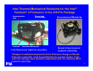
The clip, heatsink, fan, and shroud should
arrive from the supplier as an assembly.
Different heatsinks may use different clips
This assembly process is valid for the Intel Reference
components only.
The heatsink should have TIM (thermal
interface material) pre-applied to its base.
Ensure that clip levers are in open position
prior to installation on the motherboard.
The assembly should be placed over the
processor and pushed down to engage the
clip hooks with the RM windows.
The clip hooks should snap into place. Use
visual or tactile inspection to ensure that all
four hooks have fully engaged.
Actuate clip levers (2 places) by rotating the
lever into its closed position. Levers should
be rotated until encountering hard stop.
Levers can be actuated sequentially or
simultaneously. Note that the preload is
applied through engagement of the two clip
levers described above. No special
instruction is required.
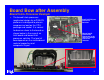
Ensure processor heat spreader contacts
heatsink base.
Refer to your board documentation to locate
the CPU fan header, and connect the fan
power cable to it.
Whenever possible, it is recommended to attach the
board to the chassis before installing the heatsink.