
Installation Manual (478-Pin Package) - All Languages
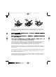
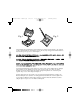
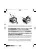
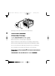


Fig. 1
m
P
G
A
4
7
8
B
Fig. 2
The heatsink may have thermal interface material attached to the bottom as shown in Figure 1. (Be careful not
to damage the thermal interface material.) If not, use the enclosed syringe and apply all of the thermal interface
material to the top of the processor as shown in Figure 2.
Le bas du dissipateur thermique peut être équipé d’une couche en mousse pour une meilleure interface thermique
(faites attention à ne pas l’endommager). Si cette couche en mousse n’existe pas, réalisez cette interface
thermique à l’aide de la seringue fournie dans la boîte. Appliquez l’intégralité de son contenu sur la partie
supérieure du processeur, comme indiqué sur la Figure 2.
Sul fondo del dissipatore di calore potrebbe essere stato applicato il materiale dell’interfaccia termica come
illustrato nella Figura 1 (fare attenzione a non danneggiare il materiale dell’interfaccia termica). Qualora non
sia stato applicato, utilizzare la siringa fornita in dotazione ed applicare il materiale dell’interfaccia termica
sulla parte superiore del processore come illustrato nella Figura 2.
130699 Pent 4 Warr.qx 7/20/01 10:27 AM Page 18 (Black plate)