
Intel Pentium 4 Processor 478-Pin Socket (mPGA478) Design Guidelines


Intel® Pentium® 4 Processor 478-Pin Socket (mPGA478)
R
11
3.3.5. Socket Size
The mPGA478 Socket must meet the dimensions as shown in Section 8 – Appendix Z.2, including actuation
mechanism, allowing insertion of the pins in the socket, without interference between the socket and the pin
field. The processor must sit flush on the socket standoffs and the pin field cannot contact the standoffs. The
height of the socket in the contact area is 4mm +/- 0.2mm post SMT; this height is from the motherboard to
the top of the socket contact surface.
3.3.6. Socket / Package Translation during Actuation
The Socket will be built so that the post-actuated package pin to motherboard pad distance (Y-axis) is in the
range of 0.30mm to 0.71mm. Movement will be along Y direction (refer to axes as indicated in Section 8 –
Appendix Z.2), and will be away from the point of actuation. No Z-axis travel (lift-out) of the package is
allowed during actuation.
3.3.7. Orientation in Packaging
Packaging media needs to support high volume manufacturing.
3.4. Contact Characteristics
3.4.1. Number of Contacts
Total number of contacts: 478
3.4.2. Base Material
High strength copper alloy.
3.4.3. Contact Area Plating
Contact area plating consists of 0.762mm (30min) (min) gold plating over 1.27mm (50min) (min) nickel
underplate in critical contact areas (area on socket contacts where processor pins will mate). No
contamination by solder in the contact area is allowed during solder reflow.
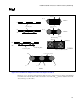
3.4.4. Solder Ball/Surface Mount Feature Characteristics
Solder ball material of Tin/Lead (either 63/37 or 60/40)
3.4.5. Lubricants
For the final product, no lubricants shall be allowed on the socket contacts. If lubricants are used elsewhere
within the socket assembly, these lubricants must not be able to migrate to the socket contacts.