
Intel Pentium 4 Processor 478-Pin Socket (mPGA478) Design Guidelines


Intel® Pentium® 4 Processor 478-Pin Socket (mPGA478)
R
17
4.2. Definitions
Table 4-2. Electrical Definitions
Item Parameter Definition
1. Mated loop inductance, Lloop The inductance calculated for two conductors,
considering one forward conductor and one return
conductor.
2. Maximum mutual capacitance, C
Refer to Section 4.2 – Definitions
The capacitance between two pins/connectors.
3. Final mated connection resistance (average of
minimum 40 pin/connector connections)
This is the final resistance after any environmental
and/or shock & vibration testing. The final mated
connection resistance specifications listed in Table 4-1
must be met for either the Kovar or
Cu alloy pin daisy
chain Package Test Vehicle.
Socket:
The resistance of the socket contact, interface
resistance to the pin, and the entire pin to the point
where the pin enters the package; gaps included.
4. Measurement frequency(s) for capacitance. Capacitively dominant region. This is usually the lowest
measurable frequency. This should be determined from
the measurements done for the feasibility.
5. Measurement frequency(s) for inductance. Linear region. This is usually found at higher frequency
ranges. This should be determined from the
measurements done for the feasibility.
4.3. Socket Electrical Characterization
Socket electrical requirements are measured from the socket-seating plane of the package to the component
side of the socket PCB to which it is attached. All specifications are maximum values (unless otherwise
stated) for a single socket pin, but includes effects of adjacent pins where indicated. Pin and socket
inductance includes exposed pin from mated contact to bottom of the processor pin field.
4.4. Electrical Resistance
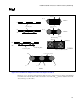
Figure 4-1 and Figure 4-2 (below) show the proposed methodology for measuring the final electrical
resistance. The methodology requires measuring package Test vehicle (PTV) flush-mounted directly to the
motherboard fixtures, so that the pin shoulder is flush with the motherboard, to get the averaged jumper
resistance, R
jumper
. The R
jumper
should come from a good statistical average of 30 PTV fixtures flush mounted
to a motherboard fixture. The same measurements are then made with an PTV fixture mounted on a supplier’s
socket, and both are mounted on a motherboard fixture; this provides R
Total
. The resistance requirement, R
Req
,
can be calculated for each chain as will be explained later.