
Intel Pentium 4 Processor 478-Pin Socket (mPGA478) Design Guidelines


Intel® Pentium® 4 Processor 478-Pin Socket (mPGA478)
R
24
Chain
No.
Socket Positions Daisy
Chained
# of
pins/chain
DC Endpoints
at Socket
Edge Finger:
Hi
Edge Finger: Low
Hi Low +I +V -I -V
42
H3-J3, K3-L3, M3-N3, P3-R3,
T3-U3, V3-W3
14 G3 Y3 A44 A20
1
43
H2-J2, K2-L2, M2-N2, P2-R2,
T2-U2, V2-W2
14 G2 Y2 A42 A18
1
44
J1-K1, L1-M1, P1-R1, T1-U1,
V1-W1
12 H1 Y1 A40 A16
45
AA2-AA3, AA4-AA5, AA6-AA7,
AA8-AA9, AA10-AA11, AA12-
AA13
12 AA13 AA1 A37 A38 A13 A14
46
AB2-AB3, AB4-AB5, AB6-AB7,
AB8-AB9, AB10-AB11, AB12-
AB13
12 AB13 AB1 A35 A36 A11 A12
47
AC2-AC3, AC4-AC5, AC6-AC7,
AC8-AC9, AC10-AC11, AC12-
AC13
12 AC13 AC1 A33 A34 A9 A10
48
AD2-AD3, AD4-AD5, AD6-AD7,
AD8-AD9, AD10-AD11, AD12-
AD13
12 AD13 AD1 A31 A32 A7 A8
49
AE2-AE3, AE4-AE5, AE6-AE7,
AE8-AE9, AE10-AE11, AE12-
AE13
12 AE13 AE1 A29 A30 A5 A6
50
AF3-AF4, AF5-AF6, AF7-AF8,
AF9-AF10, AF11-AF12
12 AF13 AF1 A27 A28 A3 A4
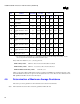
NOTES:
1. Pin Joint Resistance Circuit (Figure 4-3 – Four Different Jumpers Used in the Package Test Vehicle) – Not the
correct set up for 4-wire measurement to define the number of pins.
Daisy chains from Table 4-3 (above) are categorized as:
TYPE A Daisy Chain: Chain No. 20,21,22,23,24,25,42,45,46,47,48,49,50.
TYPE B1 Daisy Chain: Chain No. 1,2,3,4,5,6,8,9,10,11,26,27,28,29,30,31.
TYPE B2 Multi Via Pin Daisy Chain: Chain No. 7,12.
Chains 14,15,16,18,19(Pin Joint Resistance circuit), 39,40,41,43,44(TYPE A) are eliminated from the socket
electrical validation because the set up for 4-wire measurement is not correct. These are also eliminated in the
EOL Q&R test but will be monitored for FA analysis.
4.5. Determination of Maximum Average Resistance
This section provides a guideline for the instruments used to take the measurements.
Note: The instrument selection should consider the guidelines in EIA 364-23A.