
Intel Pentium 4 Processor 478-Pin Socket (mPGA478) Design Guidelines


Intel® Pentium® 4 Processor 478-Pin Socket (mPGA478)
R
25
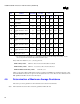
a) These measurements use a 4-wire technique, where the instruments provide two separate circuits.
One is a precision current source to deliver the test current. The other is a precision voltmeter circuit
to measure the voltage drop between the desired points.
b) These separate circuits can be contained within one instrument, such as a high quality micro-
ohmmeter, a stand-alone current source and voltmeter, or the circuits of a data acquisition system.
c) Measurement accuracy in W is specified as ± 0.1% of reading, or ± 0.1 mW, whichever is greater.
The vendor is responsible for demonstrating that their instrument(s) can meet this accuracy.
d) Automation of the measurements can be implemented by scanning the chains through the edge or
cable test connector using a switch matrix. The matrix can be operated by hand, or through software.
e) Measure R
Total
for each daisy chain of “package + socket + motherboard” unit.
f) Measure R
jumper
for each daisy chain of 30 “package + motherboard” units. Calculate the mean of
R
jumper
(
jumper
R ) from 30 measured sandwich units for each daisy chain.
g) For each socket unit, calculate
N
RR
R
jumper
Total
Req
−
=
h) R
Req
is the average contact resistance for each pin of the socket.
i) N is the number of pins per chains.
j) R
jumberBar
is the average resistance per chain of 30 measured sandwich units.
4.6. Inductance
Loop inductance of the socket pin is measured from the solder ball side of the socket using a resistance daisy
chain test fixture to short the two socket pins as shown in Figure 4-6 (
below). Figure 4-6 (below) shows the
inductance measurement fixture cross-section and the inductance measurement methodology. The first figure
shows the entire assembly. The second figure shows the assembly without the socket. This is used to
calibrate out the fixture contribution. The materials for the fixture must match the materials used in the
processor. The probe pads are the solder balls of the socket, and the shorting plane exists on the bottom side
of the daisy chain test fixture. The resistance daisy chain test fixture is cut into 24x6 pins configuration and
mounted on the socket as shown in Figure 4-7 –
Inductance Fixture Design mounted on the socket. Loop
inductance is measured from the ball side of any two pins that are shorted through a shorting bar of the daisy
chain test fixture, as shown in Figure 4-8 –
Test fixture mounted bottom view with the pins cut.